Most were manufactured by PZL-Mielec in Poland.
WSK-PZL-Kalisz (Wytwornia Sprzetu Komunikacyjnego-PZL-Kalisz)
Shvetsov ASz-62 IR Geared 9 Cylinder 1823 Cu. In. Radial Engine, rated
at 1000 HP max,
driving a 4 blade AW-2 Propellor.
_________________________________________
Propellor Gear Ratio
0.637 to 1 11:16
1800 RPM and 800 mm Hg manifold pressure
for typical climb.
1600 RPM and 700 mm Hg for typical
cruise.
Use 100 Octane Aviation Grade minimum.
Wings are of an unequal span single bay biplane design, all metal construction,
with fabric covering.
Fuselage is of all-metal stressed skin semi-monocoque construction.
Tail is a braced all metal structure with fabric covering. Wing area is
770 square feet total.
Note: wings have full length leading edge
slats and ailerons droop with flap actuation to provide great STOL performance.
Controls:
Ailerons, rudder, and elevators are all manually controlled with pushrods
and cables. Flaps and trim electrically operated. Automatic leading edge
slats provide excellent slow speed safety and high lift.
Landing Gear:
Conventional configuration (tail wheel design) with split axle, long
stroke oleo shock absorbers on the main mounts and a fully castoring and
self centering tail wheel. Brakes are pneumatically operated.
Crew: Normally two pilots, may be flown single pilot when no passengers are aboard.
Dimensions:
Length= 41 feet, 9 inches; Wing Span= 59 feet, 8 inches; Height=
13
feet, 2 inches (tail down).
Total Wing Lift Area=256.6 sq. ft. 156.2
upper 100.4 lower
Cargo compartment= 13.5 feet long by 5 feet wide by 5.9 feet tall (398.25
cubic feet).
Cargo door opening: 4.5 feet wide by 5 feet tall.
Weights:
Empty= 7,600 lbs.; Max Take Off= 12,125 lbs.; Max Landing= 11,574 lbs.;
Max fuel= 2,000 lbs. (312 USG);
Oil Qty.=22 Gallons Max. (13 Gallons minimum to 18 Gallons
normal.)
Useful load with max fuel= 2,525 lbs. (3500 lbs with half fuel carried).
Compressed Air System: 8 liter (490 Cu.In.)
Air Cylinder at 49 bars (711 PSI) maintained
by engine driven AK-50M compressor and AD-50
relief valve. Pressure gauge is on pilot's
left hand console. A pressure reducer supplies
10 bars (145 PSI) for the main brakes.
The Air Pressure is required for the pneumatic
main wheel brakes, but can be used to
charge the landing gear shock absorbing oleo-pneumatic
struts when dry nitrogen is
not available. A fitting is also available
to fill the tires from this system. The 8 liter
air cylinder can also be charged from appropriate
ground support equipment.
Electrical System: 24 VDC battery with engine driven generator
to maintain charge.
Voltmeter and Ammeter on Instrument Panel.
The 28 VDC generator requires at least 900-1000 RPM to kick in.
36 Volt 3 phase 400hz AC power, supplied by two convertors, is used
to power the Russian Gyroscopic compass, Artificial Horizon and ADF.
CO2 Fire Extinguishing System with automatic fire detector: Nine fire detectors are located throughout the engine compartment. If the Fire Warning Lamp light, the CO2 system can be activated by breaking the safety seal and pushing the button. The CO2 bottle has an electrically activated pyro-technic cartridge to release the CO2 into the collector. Portable CO2 Fire Extinguishers are normally installed in the cockpit and cabin as well.
Oil Cooling System: The Oil System consists of a 125 liter (33
gal) Max. permitted
22 gal. tank, suction pump and an external Oil Cooler with electrically
controlled shutters.
Use Aeroshell 100 Oil.
The following data applies to all An-2s except float versions which
have reduced performance and load capacities.
Data is based on a typical weight of 11,600lbs. in mid-mission.
Red Line Speed: V-NE
162 kts.
White Line Flaps: V-FE
70 kts.
Best Glide:
65 kts.
Maximum Speed: 139kts. or
160mph. (120kts. more typical)
Economy Cruise Speed: 100kts.
or 115mph. (95kts. more typical)
Minimum Speed: 49kts. or
56mph.
Take-Off Speed: 43kts. or
50mph. (15 degrees of flap).
Landing Speed: 46kts. or
53mph. (30 degrees of flap).
Stall Speed: 35-40kts. but
controlled descents are possible at 25kts. or 30mph.
Typical SL Take-Off
distance to clear 50 foot obstacle: 1600 feet.
Great STOL performance!
Minimum SL Take-Off
Run: 560 feet.
(We've done 275 feet
roll, empty in 15kt. Head Wind)
Typical SL Landing
distance over 50 foot obstacle: 1400 feet.
Normal Range: 485nm
with 45 min. reserve.
(550nm max with approx.
6 hours endurance).
Max SL Rate of Climb:
680 fpm, 30 minutes to 14,425 feet.
Ceiling: 14,425 feet
with 1,100lbs. of cargo.
(we've managed 9,500
feet with 2500lb. load in Guatemala).
Note: Tolerable
Cross wind component is only 8 kts with full flaps. Aircraft cannot be
taxied with
wind in excess of 20 kts.
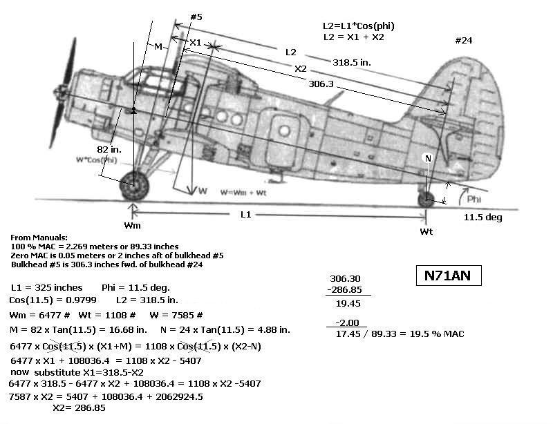
In practice, however, this procedure is difficult
and hazardous since the tail wheel must be
lifted about 66 inches off the ground to level
the aircraft. ( forcing bulkhead #5 to be vertical.)
Using some mathematics and trigonometry, we
can avoid having to jack the AN-2 tail
high into the air. We can get the answer by
jacking the tail only a foot or two high.
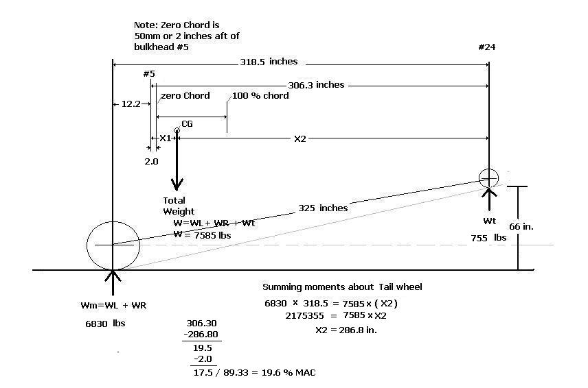
Summing moments about the tail wheel, the Weight
on the Mains must counteract the Total Weight
of the aircraft at the CG. (see figure below).
Total Wt. = Weight on Mains plus Weight on Tail wheel.
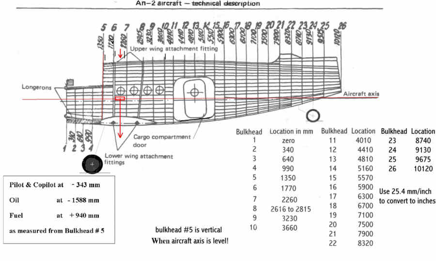
The tail wheel is at about bulkhead # 24 (9130mm) so distance to
bulkhead #5 (1350mm) = 7780mm
or 306.3 inches.
In three point attitude the distance L1 from tail wheel axle to main
gear axle line is 325 inches and
the angle Phi is about 11.5 degrees.... L2 = L1 * Cos(11.5
deg) = 318.5 inches.
Thus L2 extends from tail wheel axle to 12.2 inches forward of bulkhead #5.
The Aircraft manual defines thebeginning of
the Mean Aerodynamic Chord as being 2 inches aft
of Bulkhead #5. The total length of the MAC
is 2.269 meters or 89.93 inches.
We also need to know the height of CG as it may not be on the center
line of the aircraft.
(From the two aircraft we have measured, it turns out that the
cg is very near the aircraft center
line....about 80 inches above the main gear axle... aircraft
in level flight attitude.)
The weight on the mains will increase as we lift the tail. The amount
of increase is affected by the
height of the CG as well as its distance behind the main gear axle.
Scales will need to accommodate up to 5000 pounds.
This procedure should be carried out for an EMPTY aircraft.
(1) After calibrating and placing scales under each wheel, measure
distance from tail wheel axle
to main gear imaginary common axle. This is L1 and it should be
approximately 325 inches.
(varies slightly with strut fill)
(2) Measure angle of bulkhead #5 which separates cockpit from cabin.
It should be approximately
11.8 degrees off of vertical. (varies slightly with main strut lengths)
(3) Sum the weights on the Mains to get Wm. Record this number and
the weight on tail, Wt.
Sum all three weights to get W.
(4) Now jack the tail up until the sum of the weight on the
main gear increases by 100 pounds
this required a height of 19 inches in our example. Record
the new weight on the mains and
the height that the tail wheel was raised above the tail scale.
(5) Enter the data into the AN-2
Center of Gravity Calculator excel sheet and it will calculate
the cg location and the % mean aerodynamic chord.
Click here to Down load the AN-2
CG Calculator Excel sheet
Empty CG should be between 17 and 24 % MAC.....
Fully loaded CG should be between 20 and 30 % MAC
(Do not attempt parachute mode descent
.. full flaps, full elevator.... with CG aft of 30
%!)
Fwd. CG limit = 17 % MAC!
Aft CG absolute limit = 32 % MAC
Using Bulkhead 5 as reference:
Weight Arm
Moment
Aircraft with Oil
7587 + 19.45
= +147567
removing Oil
-120 - 63.0
= + 7560
_____________________________________________
7467
+155127
155127 / 7467 = 20.77 in. arm
Hence N71AN empty baseline is:
Using Bulkhead 5 as reference:
Weight Arm
Moment
Empty Aircraft
7467 +20.77
= + 155127
Once the Center of Gravity has been determined
for the EMPTY aircraft, weight and balance
calculations for the loaded aircraft can be
calculated.
Assume this Aircraft has empty weight of 7465 lbs. and CG is
20 inches aft of bulkhead 5.
This is equivalent to a typical AN-2 utility aircraft ( 20.15 %
MAC EMPTY)
Bulkhead #5, the bulkhead separating the cockpit
from the main cabin, is used as the point of
reference in these calculations.
Fwd of # 5 will be negative... Aft of #5 will be positive.
Use 7.5 lbs/ gallon for weight of Oil ..... 100 liters = 26.42 gallons = 198 lbs.
TABLE:
weights inches from #5
Moment
___________________________________________________________
Typical Empty AN-2
7465 lbs.
+20
+ 149,300 in.lbs.
Crew
380 lbs.
-13.2
- 5,016
Oil
(16 gal.)
120 lbs.
- 62.4
- 7,488
Fuel (200 gal.)
1200 lbs. +
37
+ 44,598
Cargo
1000 lbs. +100
+ 100,000
____________________________________________________________
10,165 lbs.
+ 281,394
CG = Sum of Moments / Sum of Weights = 281,394 / 10,165 = 27.68 inches aft of #5
Note: beginning of chord is 2 inches aft of bulkhead #5... so we subtract 2 inches...
% MAC = 27.68 - 2 / 89.33 = 25.68 / 89.33 = 0.2875 or 28.75 % MAC
Limits are 17% to 32 %
Recommended range is between 23% and 27%......
Weight and Balance measurements with aircraft tail jacked up to level............
Excel worksheet for AN-2 in level attitude.
This figure is useful in determining location of aircraft loads.....
This page still under development...............